Housing project of the dynamic seal
Dynamic liquid seal
In the dynamic seal applications (those applications in which relative movement is present between the seal system parts) the O-Ring is found subject to provoked friction from the long flow of the seal surface. This makes the working conditions more critical with respect to static applications; consequentially in the realization of the lodging seals of these gaskets more attention must be paid and a higher precision attained.
The O-Rings are not used in "flange seal" conditions when one deals with the exercising of the seals between the elements in the relative motor, therefore we address our attention to the solicitation of radial pre-load, dimensioning the housings for the cylinder seal and the piston seal.
In figure 4.11 and 4.12 the details of the realized housings for the dynamic cylinder and piston seals are shown, when the system is realized for the liquid seals.
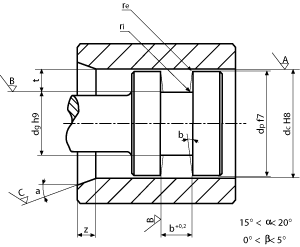 Figure 4.11
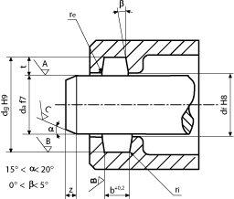 Figure 4.12
As in the case of static seal applications, it is a good rule to avoid that the deformations of the circumference in the working setting exceeds 3% for the compressed circumference and 6% for the stretching process.
In the choice of the best O-Ring for the application, it is not to be forgotten the possibility that the fluid to be contained could interact with the compound of the O-Ring provoking the variation of volume, therefore, a variation of the compression load transmitted from the seal's surface. In figure 4.13 the values of the recommended percentage of flattening are carried forth in the application of dynamic liquid seals, to guarantee a good working and limiting the friction.
In the choice of the best O-Ring for the application, it is not to be forgotten the possibility that the fluid to be contained could interact with the compound of the O-Ring provoking the variation of volume, therefore, a variation of the compression load transmitted from the seal's surface. In figure 4.13 the values of the recommended percentage of flattening are carried forth in the application of dynamic liquid seals, to guarantee a good working and limiting the friction.
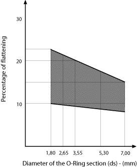 Figure 4.13
In Table 4.7 the finishing qualities of the recommended working for the execution of the housing walls are indicated. More precisely the rugosity class and the Ra value relative to the housing wall are shown, at the bottom and on the surfaces that oppose them and that determine the deformation of pre-load. As discriminate for the compilation of the table, we have assumed that the support area of the O-Ring is at least 50% of the ideal value.
In Table 4.8 shows the geometric parameter values of the housing, rather its width, joint radius and the length of the entry bevel in relation to the diameter ds of the O-Ring. The underlined values represent the diameters of the recommended work by the ISO and DIN regulations.
In Table 4.8 shows the geometric parameter values of the housing, rather its width, joint radius and the length of the entry bevel in relation to the diameter ds of the O-Ring. The underlined values represent the diameters of the recommended work by the ISO and DIN regulations.
Dimensional table for the dynamic liquid holding
In the next table which we refer to, as already carried out for the applications of the static seals, the parameters for correct project of the O-Ring housings and of the seal systems are indicated:
- Table 4.9 – dimensions of the housing to be executed in function of the standard O-Rings diameters of our production, without, with one or with two anti-extrusion rings;
- Table 4.10 – dimensions of the housing and the particulars for the element realization for the static radial and axial housing.
Dynamic gas seal
For the seal in pneumatic systems, and more in general of gas, to limit the friction the piston seal with "floating" O-Ring is used, or without contact with the base of the housing (figure 4.14).
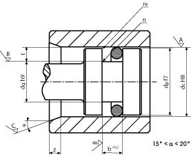 Figure 4.14
For the seal of gas, the O-Ring works with a little flattening of the circumference, a pressing which is accepted not greater than 6% of the circumference value and non inferior than 4%. In figure 4.15, we refer to the recommended percentage flattening values in the applications of dynamic seal in the pneumatic circuits with "floating" rings.
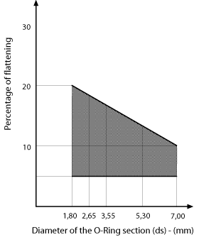 Figure 4.15
In Tables 4.11 and 4.12 the dimensional values and superficial finishing of the O-Rings housings are shown in the applications of Dynamic gas seal.
In Tables 4.13 and 4.14 the recommended values for the floating assemble of the O-Ring are shown.
In Tables 4.13 and 4.14 the recommended values for the floating assemble of the O-Ring are shown.
Dimensional table for the dynamic seal of gas
In the next table which we refer to, as already carried out for the applications of the static seals, the parameters for correct project of the O-Ring housings and of the seal systems are indicated:
- Table 4.15 – dimensions of the housing to be executed in function of the standard O-Rings diameters of our production, without, with one or with two anti-extrusion rings;
- Table 4.16 – dimensions of the housing and the particulars for the element realization for the static radial and axial housing.
Technical sheets
- Table 4.7
- Table 4.8
- Tables 4.9 and 4.10 [part 1 of 5]
- Table 4.10 [part 2 of 5]
- Table 4.10 [part 3 of 5]
- Table 4.10 [part 4 of 5]
- Table 4.10 [part 5 of 5]
- Tables 4.11, 4.12, 4.13 and 4.14
- Tables 4.15 and 4.16 [part 1 of 5]
- Table 4.16 [part 2 of 5]
- Table 4.16 [part 3 of 5]
- Table 4.16 [part 4 of 5]
- Table 4.16 [part 5 of 5]
Elastotech Srl -
+39 035 4496000 - info@elastotech.it - VAT IT03812040164 - cookies - privacy - credits
Via Provinciale, 92/94 - 24060 Castelli Calepio, Bergamo, Italy
+39 035 4496000 - info@elastotech.it - VAT IT03812040164 - cookies - privacy - credits

Elastotech Srl
Via Provinciale, 92/94 - 24060 Castelli Calepio (BG) Italy
Tel. +39 035 4496000 - info@elastotech.it
P.IVA/VAT IT03812040164 - Reg. Imp. Bergamo 410502
Cap. Soc. i.v. € 270.000,00
cookies - privacy - credits
Via Provinciale, 92/94 - 24060 Castelli Calepio (BG) Italy
Tel. +39 035 4496000 - info@elastotech.it
P.IVA/VAT IT03812040164 - Reg. Imp. Bergamo 410502
Cap. Soc. i.v. € 270.000,00
cookies - privacy - credits
Elastotech Srl -
+39 035 4496000 - info@elastotech.it - VAT IT03812040164 - cookies - privacy - credits
Via Provinciale, 92/94 - 24060 Castelli Calepio, Bergamo, Italy
+39 035 4496000 - info@elastotech.it - VAT IT03812040164 - cookies - privacy - credits
Elastotech Srl
Via Provinciale, 92/94 - 24060 Castelli Calepio (BG) Italy
Tel. +39 035 4496000 - info@elastotech.it
P.IVA/VAT IT03812040164 - Reg. Imp. Bergamo 410502
Cap. Soc. i.v. € 270.000,00
cookies - privacy - credits
Via Provinciale, 92/94 - 24060 Castelli Calepio (BG) Italy
Tel. +39 035 4496000 - info@elastotech.it
P.IVA/VAT IT03812040164 - Reg. Imp. Bergamo 410502
Cap. Soc. i.v. € 270.000,00
cookies - privacy - credits