Housing project of the static seal
The characteristics of the O-Ring type of gaskets prove to be particularly suitable the job in static applications. The efficiency of the seal of the O-Ring depends upon, as it has been described in the previous chapter, various factors from which: the nature of the fluid with which is in contact and their chemical action in the elastic compound, the maximum and minimum temperature to which they are required to work, the type of material of the combining elements and the accuracy with which the housings that hold them are realised. Another very important factor into guaranteeing the seal is the correct dimensions of the O-Ring and therefore the correct choice of ds and di values (figure 4.5) in relation to the geometric characteristics of the combining elements.
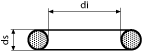 Figure 4.5
In the radial static seal applications the O-Ring is inserted into a housing that can be derived both on the element which constitutes the shaft, as well as on the inside of the hole that houses it. Once positioned in the housing, the O-Ring receives a push from the combining elements which deforms it in a radial sense. Based on the pressure exercised from the fluid, the O-Ring that guarantees the seal with compressed percentage flattening in the interval indicatively represented in figure 4.6 is chosen.
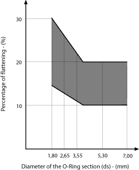 Figure 4.6
The dimensions of the housing is determined by the diameter of the O-Ring section and of the flattening to which it is subjected to. Also the exercised pressure of the system is determined: increased pressures can intervene to modify the play between the parts and therefore influence the pre-load set in the project phase.
Radial static seal
Figure 4.7 shows the housing of an O-Ring obtained on the shaft to attain that which was defined as "piston seal". In the said figure, the recommended working tolerance values are indicated for the combining hole/shaft, the joint radius, the inclination and the finishing level of the housing.
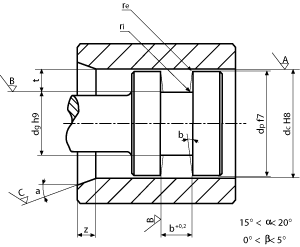 Figure 4.7
Figure 4.8 shows the same parameters for the combination defined as "cylinder seal".
In both the figures, the bevel to put into practice to combine the elements without damaging the O-Ring is indicated.
In both the figures, the bevel to put into practice to combine the elements without damaging the O-Ring is indicated.
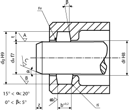 Figure 4.8
The parameter values of figure 4.7 and 4.8 are carried back in Tables 4.1 and 4.2.
In Table 4.1 the recommended working finishing level of the housing walls are indicated. More precisely, the rugosity class is shown along with the Ra value relative to the housing walls, at the end and on the surfaces that oppose them and which determine the deformation of the pre-load. As discriminate for the compiling of the table, we have assumed that the O-Ring support area is at least 50% of the ideal value.
The Table 4.2 shows the geometric parameter values of the housing, rather its width, the joint radius and the length of the entry bevel in relation to the O-Ring diameter ds. The underlined values represent the diameters of the post recommended by the ISO and DIN regulations.
Static axial seal
The O-Rings that are used for the "flange seal", therefore with perpendicular pre-load pressure at the ring level, undergo different solicitations according to the applications they are used in which the pressure acts from the inside of the ensemble rather than the outside. This difference in behaviour leads us to consider the two situations separately.
In figure 4.9 the housing for the O-Ring is represented in the case where the fluid pressure acts from the inside. In this circumstance, the housing for the O-Ring undergoes a compression. In order that the O-Ring guarantees the seal it is accepted that the compression does not exceed 3% of its circumference value.
In figure 4.10 the O-Ring housing is represented in an application where the pressure acts from the outside. During the installation for this type of application, the O-Ring undergoes a stretching process that must not exceed 6% of its circumference value.
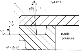 Figure 4.9
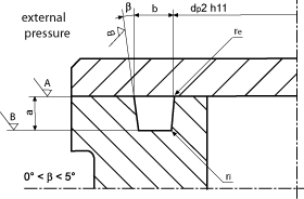 Figure 4.10
In Tables 4.3 and 4.4 the parameter values of the correct dimensioning of the housing are shown, as already shown for the seals examples seen in the previous paragraph.
Dimensional table for the static housing
To conclude the discussion regarding the static housings, we go back to two tables that we hold as useful for the designers:
Technical sheets
Elastotech Srl -
+39 035 4496000 - info@elastotech.it - VAT IT03812040164 - cookies - privacy - credits
Via Provinciale, 92/94 - 24060 Castelli Calepio, Bergamo, Italy
+39 035 4496000 - info@elastotech.it - VAT IT03812040164 - cookies - privacy - credits

Elastotech Srl
Via Provinciale, 92/94 - 24060 Castelli Calepio (BG) Italy
Tel. +39 035 4496000 - info@elastotech.it
P.IVA/VAT IT03812040164 - Reg. Imp. Bergamo 410502
Cap. Soc. i.v. € 270.000,00
cookies - privacy - credits
Via Provinciale, 92/94 - 24060 Castelli Calepio (BG) Italy
Tel. +39 035 4496000 - info@elastotech.it
P.IVA/VAT IT03812040164 - Reg. Imp. Bergamo 410502
Cap. Soc. i.v. € 270.000,00
cookies - privacy - credits
Elastotech Srl -
+39 035 4496000 - info@elastotech.it - VAT IT03812040164 - cookies - privacy - credits
Via Provinciale, 92/94 - 24060 Castelli Calepio, Bergamo, Italy
+39 035 4496000 - info@elastotech.it - VAT IT03812040164 - cookies - privacy - credits
Elastotech Srl
Via Provinciale, 92/94 - 24060 Castelli Calepio (BG) Italy
Tel. +39 035 4496000 - info@elastotech.it
P.IVA/VAT IT03812040164 - Reg. Imp. Bergamo 410502
Cap. Soc. i.v. € 270.000,00
cookies - privacy - credits
Via Provinciale, 92/94 - 24060 Castelli Calepio (BG) Italy
Tel. +39 035 4496000 - info@elastotech.it
P.IVA/VAT IT03812040164 - Reg. Imp. Bergamo 410502
Cap. Soc. i.v. € 270.000,00
cookies - privacy - credits